CALCULATION
Overview
Challenge
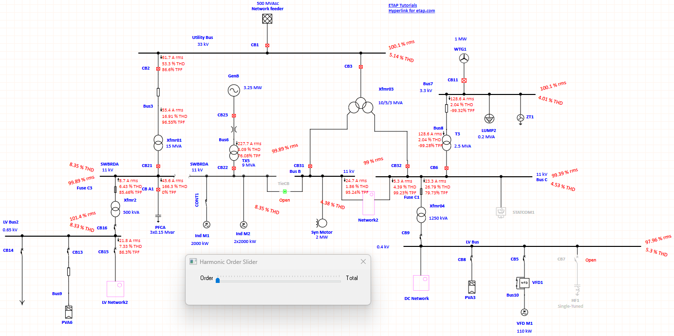
Harmonic and resonance analysis is used to verify power system design and existing installations against power quality standards.
It is required for:
- grid connection compliance
- verification against regulatory requirements
- evaluation of equipment operating conditions
- prevention of overloads and premature failures
What it means
In real power systems, voltage and current waveforms are not perfectly sinusoidal.
Power electronic devices (VFDs, UPS systems, thyristor-controlled equipment) introduce higher-order harmonics.
In simple terms:
- waveform distortion occurs
- additional frequencies appear
- equipment operates under increased stress
These effects are quantified using Total Harmonic Distortion (THD).
What is analyzed
A digital model of the power system is developed to:
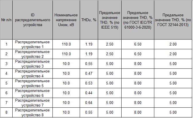
- calculate THD levels
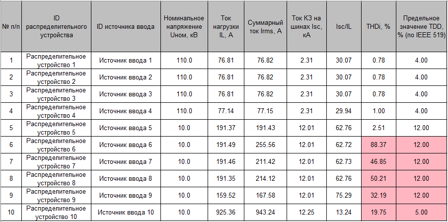
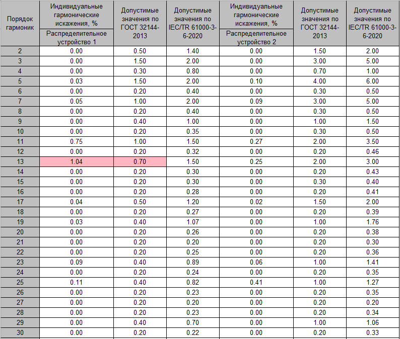
- evaluate individual harmonic components
- assess equipment impact
- analyze resonance conditions
Results
Results are provided in tabular and graphical formats.
Values exceeding acceptable limits are clearly highlighted.
Resonance Analysis
To evaluate resonance risks:
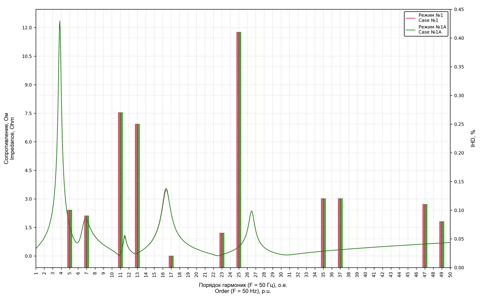
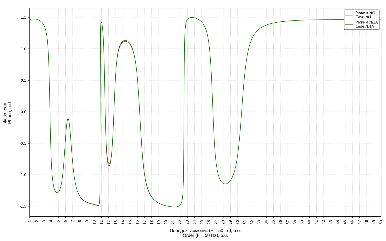
- frequency response characteristics are calculated
- phase response characteristics are analyzed
- harmonic spectra are superimposed on response curves
This allows to:
- identify resonance frequencies
- assess system sensitivity
- determine critical operating conditions
When the Study is Required
- installation of VFDs or power electronics
- connection of nonlinear loads
- system upgrades
- power quality issues
- unexplained protection trips
Deliverables
- input data description
- calculation results (tables and charts)
- compliance assessment
- conclusions and recommendations
Customer Value
- compliance with power quality standards
- reduced risk of equipment damage
- prevention of resonance conditions
- improved system reliability
- optimized filter design
Why it matters
Harmonic distortion often develops gradually but leads to:
- overheating of cables and transformers
- accelerated equipment aging
- false protection trips
- reduced equipment lifetime
Early analysis allows these issues to be identified and mitigated.
Input data
- Single-line diagram
- Generator and utility system parameters (short circuit levels, X/R ratio, etc.)
- Transformer, cable, and overhead line parameters
- Reactive power compensation equipment
- Harmonic filter parameters
- Load data and power factors
- Motor nameplate data
- Harmonic source parameters (VFDs, UPS, thyristor systems, furnaces, etc.)
- Measured or manufacturer-provided harmonic spectra
Results
- Compliance assessment with GOST, IEC, and IEEE 519 standards
- Evaluation of equipment overloading due to harmonics
- Harmonic spectra across the network
- Frequency response analysis for resonance detection
- Recommendations for harmonic filtering solutions